The product

What the engine actually does.
Discipline by discipline.

Seven MEP disciplines, designed into one BIM model in a single run - each to its own Swedish standard, each handing a finished model to the next. Below is what every one of them authors, the sheets it produces, and where each number came from.

7
disciplines in one chain
20 s
full chain, measured
514
sprinkler heads
292
air terminals
720
power outlets
0
cross-discipline clashes

Measured on demo model A-40-V-01 - 7 storeys, 42 apartments - run end to end. Nothing on this page is a mock-up.

The disciplines

Seven engineers' worth of work, in one run.

Each discipline designs into the same IFC model and hands it on. The sprinkler pipe network is still there when ventilation routes its ducts, which is why the last discipline - fire safety - can read all six that came before it.

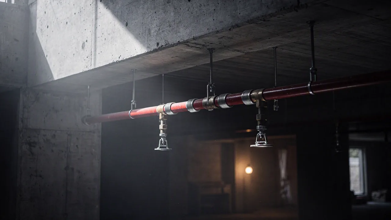
A red sprinkler main on threaded-rod hangers under a concrete soffit, with branch lines dropping to pendent heads
Illustration, AI-generated

01 / 07

Sprinkler

SS-EN 12845:2015+A1

Hazard class and design density set the head spacing; the engine places heads room by room, routes branch and distribution pipe to the riser and balances the hydraulically most demanding operating area until it converges.

514 heads across 7 storeys
  • Pendent heads, room by room
  • Branch, distribution and riser pipe with DN per section
  • Hydraulic calculation to the design point
  • Riser diagram with a valve per storey branch
  • OH1 · 5 mm/min
  • Q 442 L/min at 4.25 bar
  • 2 313.7 m pipe · DN 25–50

S-RIT-102 planS-BER-001 calculationS-STAM-001 riser

Read off S-STAM-001 and S-BER-001 below.
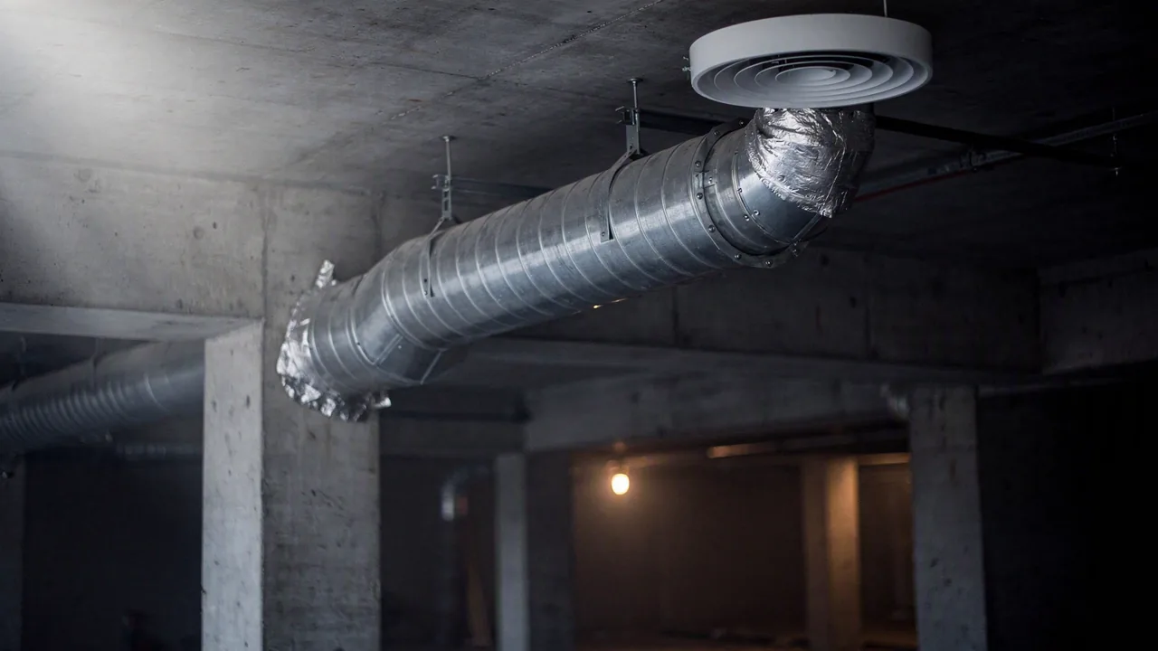
A spiral galvanised ventilation duct with a branch take-off running to a round ceiling supply diffuser
Illustration, AI-generated

02 / 07

Ventilation

BBR 6:25 · SS 25267

Air terminals are sized from the room type and its required airflow, then ducts are routed to the shaft so supply and extract balance per storey — not per room in isolation.

292 air terminals placed
  • Supply and extract terminals per room
  • Ducts to the shaft, sized per section
  • Fire dampers at compartment boundaries
  • Airflow tables and OVK inspection basis
  • Supply/extract balanced per storey
  • Room acoustics per SS 25267
  • Fire dampers at every boundary

Airflow tablesDuct plans per storeyOVK inspection basis

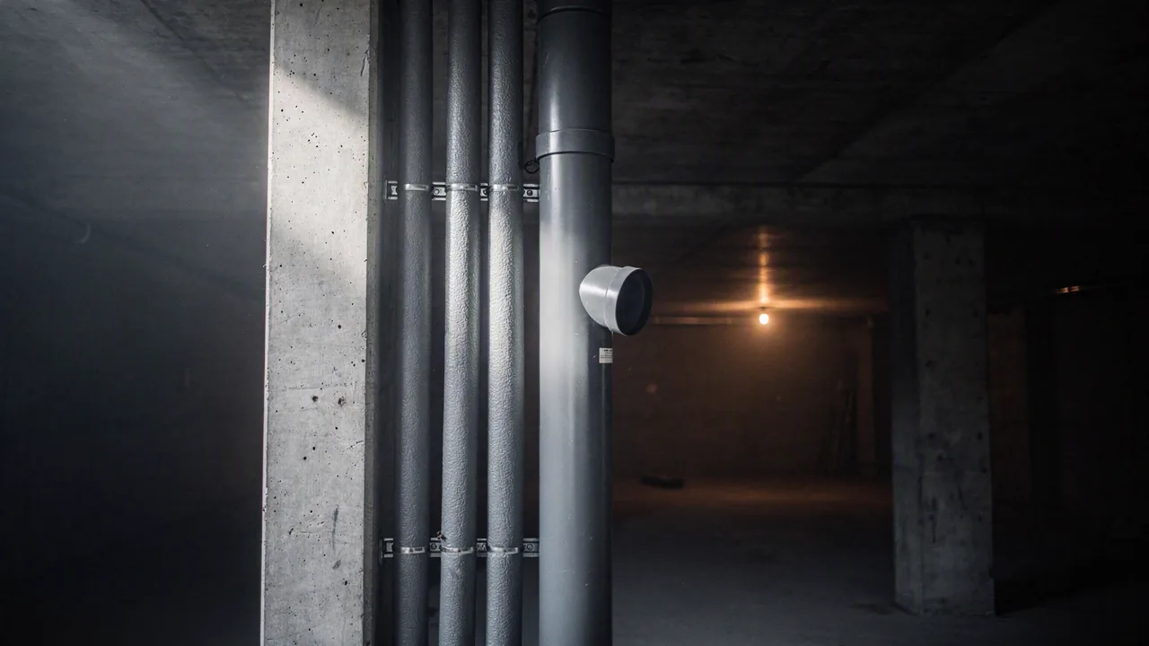
Insulated domestic water pipes running beside a grey soil stack inside a narrow service shaft
Illustration, AI-generated

03 / 07

Plumbing

SS-EN 806 · SS-EN 12056-2

Fixtures are summed to discharge units per storey, the waste stack is sized from the total, and the shaft position follows from where the stacks actually land in the model.

230.8 l/s summed discharge units
  • Potable hot and cold water with circulation
  • Waste stacks in shafts, sized from summed DU
  • Water metering at the service entry
  • Stack schematic with a branch per storey
  • Stack DN 160 · 38 floor drains
  • Circulation loop ≈ 150.6 m
  • Fall min. 1:100 to the connection point

VS-STAM-001 stack schematicPlans per storey

Read off VS-STAM-001 below.

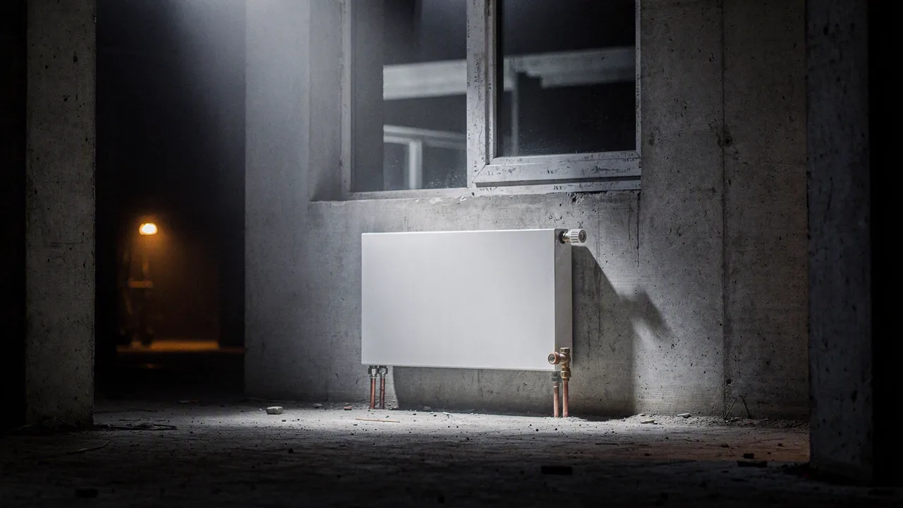
A white steel panel radiator under a tall window opening in an unfinished concrete room
Illustration, AI-generated

04 / 07

Heating

SS-EN 12831

A room-by-room heat load is computed from the model geometry and envelope, then radiators are sized and placed where they belong — under the window, not wherever there was space.

234 radiators sized and placed
  • Room-by-room design heat load
  • Radiators sized and placed under windows
  • Thermostatic valves and pipe runs
  • Heat load summary per storey
  • Load per room, not per flat
  • Placement follows the window openings
  • Feeds the plant-room duty

Heat load tablesRadiator plans per storey

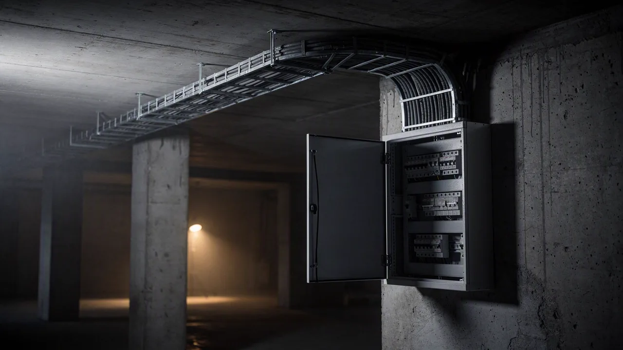
A galvanised cable ladder with combed cabling running into an open wall-mounted distribution board
Illustration, AI-generated

05 / 07

Electrical

SS 436 40 00 · SS 437 00 02

Outlets and lighting are laid out per room, grouped into apartment boards, and the boards are fed from the building board through the riser — the single-line diagram is a consequence of that layout, not a drawing exercise.

42 apartment boards · 176 groups
  • Outlets and lighting per room
  • Apartment boards with group counts
  • Riser from the building board in the shaft
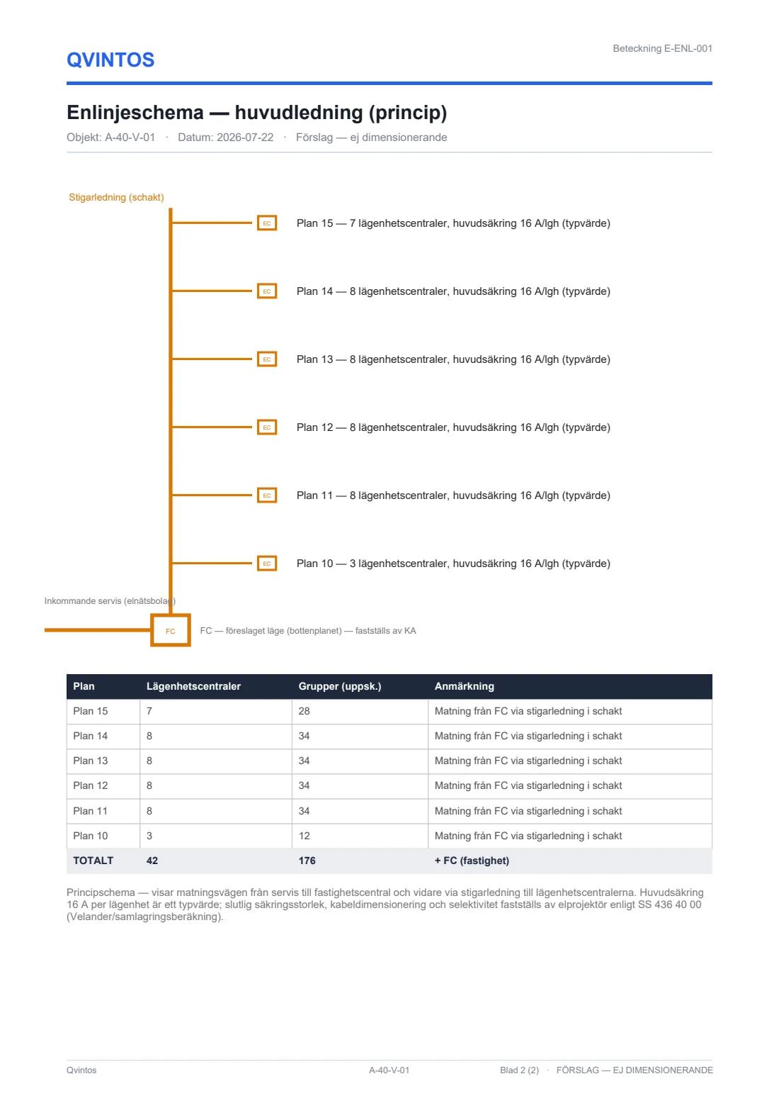
  • Single-line diagram of the main distribution
  • 720 outlets placed
  • 16 A per apartment (typical)
  • Fed from FC via the shaft riser

E-ENL-001 single-lineOutlet and lighting plans

Read off E-ENL-001 below.

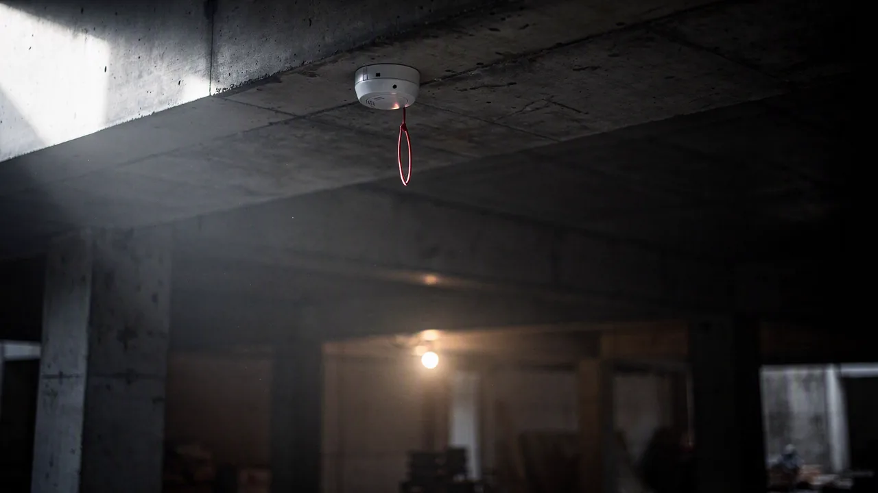
A single optical smoke detector on a concrete soffit with a slender red loop cable clipped to it
Illustration, AI-generated

06 / 07

Fire alarm

SBF 110 · SS-EN 54

Detectors follow the coverage rules for each room type, zones follow the fire compartments already in the model, and the loop is routed so the battery calculation actually closes.

200 detectors on the loop
  • Detectors per room, to coverage rules
  • Zones aligned to the fire compartments
  • Loop routing and loop diagram
  • Battery calculation for standby and alarm
  • Zones follow the compartments
  • Loop diagram per storey
  • Battery calculation included

Zone plansLoop diagrams

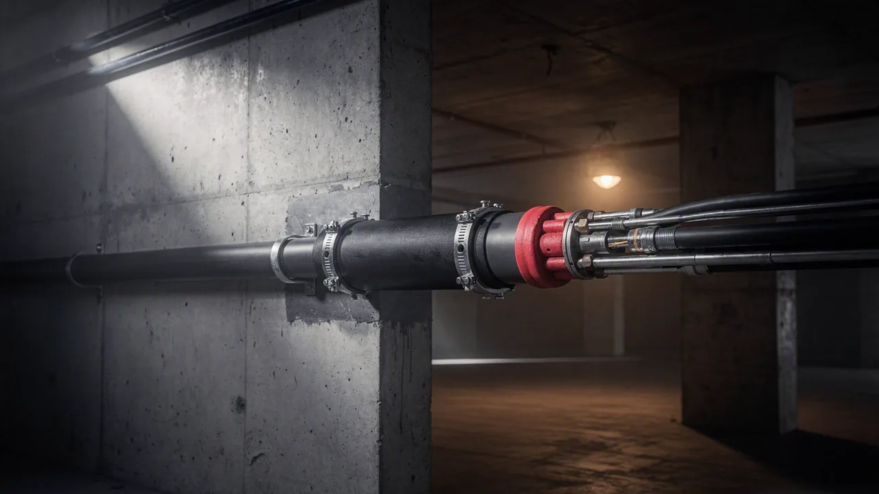
A pipe penetration through a concrete wall sealed with an intumescent collar and firestop sealant
Illustration, AI-generated

07 / 07

Fire safety

BBR 5

Fire safety reads the whole combined model — every duct, pipe and cable that crosses a compartment boundary is a penetration that has to be accounted for, which is only possible because the six disciplines before it designed into the same model.

7 of 7 disciplines read together
  • Fire-protection basis over the combined model
  • Compartment boundaries and their penetrations
  • Damper and collar requirements per crossing
  • Items that must be completed by the certified reviewer
  • Reads the combined model, not one layer
  • Every boundary crossing accounted for
  • Open items flagged, never guessed

Fire-protection basisPenetration schedules

Real output

Floor 11, exactly as the engine placed it.

Not a rendering of a drawing - the drawing. Every room outline, pipe, head, terminal and outlet below sits where the sizing engine put it on demo model A-40-V-01. Switch a layer off to see how the disciplines stack.

Plan 11 · A-40-V-01 · 81 heads on this storey

Generated by the engine, not drawn by hand. The same geometry is what gets written back into the IFC.

Coordination

Coordination is geometry, not a meeting.

In the normal process, seven consultants each model in their own file and the clashes surface at a coordination meeting weeks later. Here the duct is routed in a model that already contains the sprinkler main and the cable ladder, so the conflict cannot be created in the first place.

20 s
one run, seven disciplines
0
cross-discipline clashes
6
handovers that never happen
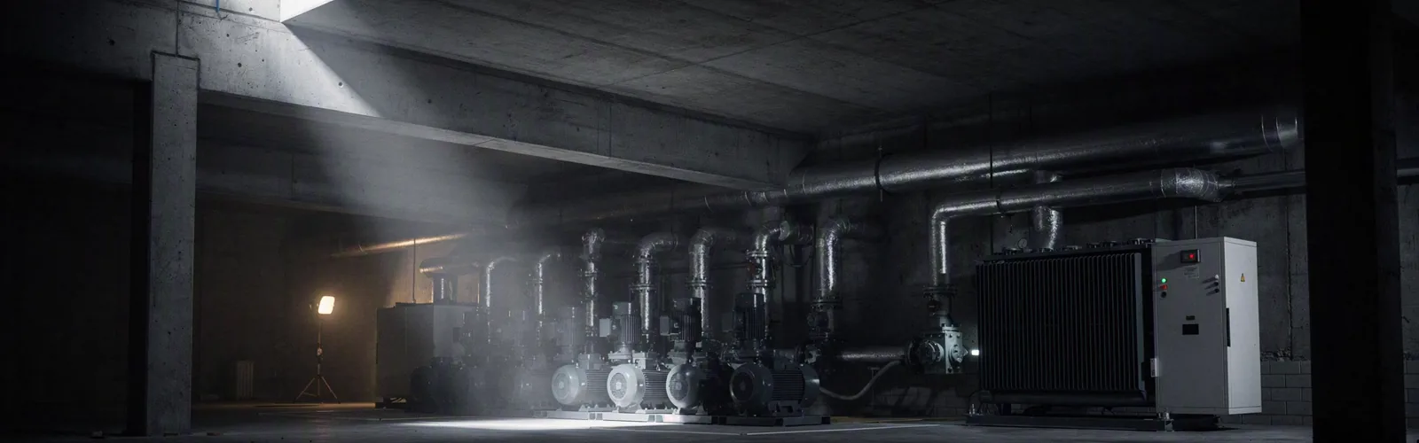
Duct, sprinkler main and cable tray sharing one soffit. Illustration, AI-generated.

The delivery

Finished documents. Not export files.

These five sheets are the engine's untouched output on the demo model. Title block, legend, scale, status stamp - and a quantity panel whose figures you can check against the schematics on either side of it.

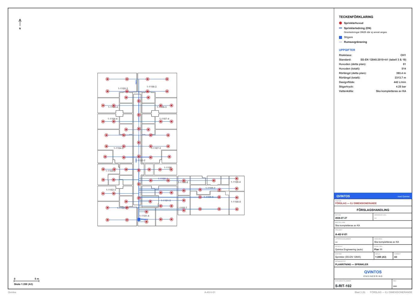
A sprinkler floor-plan sheet with title block, legend and quantity panel
S-RIT-102 · Sprinkler plan, Floor 11 A3 to scale, with title block, legend and the plan's own figures — 81 heads on this storey, 393.4 m of pipe, riser pressure 4.25 bar.
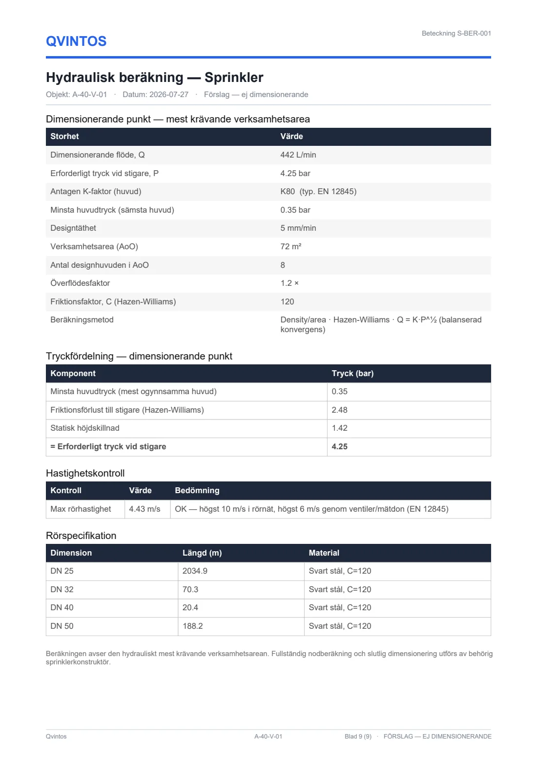
A hydraulic calculation appendix with tables for design point, pressure distribution and pipe schedule
S-BER-001 · Hydraulic calculation Design point, pressure distribution, velocity check and pipe schedule — every line traceable to the network above.
A sprinkler riser schematic with a branch and valve per storey
S-STAM-001 · Sprinkler riser diagram Riser DN 50 with a shut-off per storey branch, head count per storey, 514 in total.
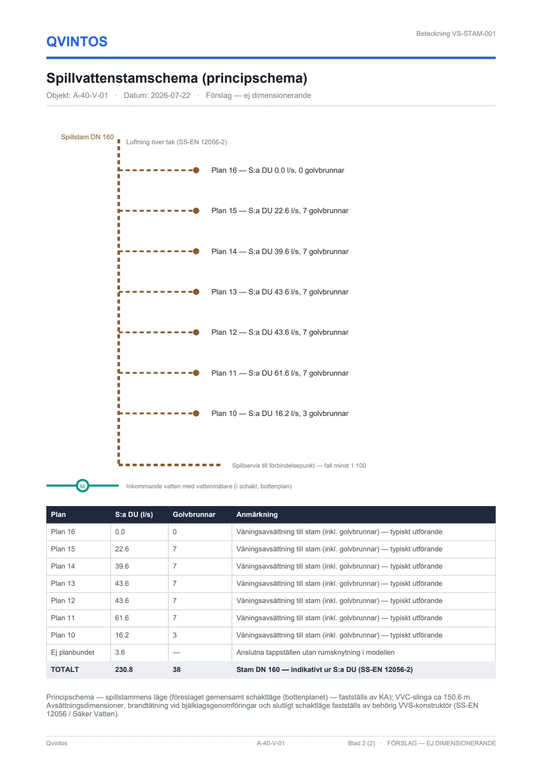
A waste stack schematic with discharge units per storey
VS-STAM-001 · Waste stack schematic Summed discharge units per storey to a DN 160 stack, vented above roof, 38 floor drains.
An electrical single-line diagram from the incoming service to the apartment boards
E-ENL-001 · Single-line diagram Service to building board to riser to 42 apartment boards, 176 groups, 16 A per apartment.
Macro of the corner of a printed drawing sheet

The sheets are in Swedish. That is the feature.

A Swedish permit process expects Swedish documents, reviewed by a Swedish certified reviewer against Swedish standards. So the deliverables are produced in Swedish no matter what language you read the platform in - translating them would make them worth less, not more.

Formats

Open in, open out.

Nothing is locked to us. The model goes back out as IFC with the MEP authored in, and the sheets are ordinary PDFs your reviewer already knows how to read.

In

  • IFC (2x3 / 4)
  • PDF drawings
  • DWG
  • Specifications & schedules

Out

  • IFC with the MEP model authored in
  • PDF sheets, A3 to scale
  • DWG
  • XLSX quantity and airflow tables
A dark equipment rack with network patch ports
Illustration, AI-generated

Traceability

Why you can check every number.

An AI that invents a plausible pipe diameter is worse than no AI at all, because the mistake looks like work. Four mechanisms make that structurally hard here - not four promises.

Provenance is a data structure, not a footnote

Every figure the engine writes carries the element, the rule and the standard clause it came from. A number without a source cannot be written to a sheet — the path simply has no branch for it.

"Ska kompletteras av KA" is a literal output

Where an input genuinely is not in the model — the water source, the client, the responsible reviewer — the sheet says so, in those words. The engine never fills a gap with a plausible value.

Uncertainty is reported, not smoothed away

Typical values are marked as typical. Indicative sizing is marked as indicative. Every sheet carries the status stamp FÖRSLAG — EJ DIMENSIONERANDE until a certified engineer signs it.

Fabrication fails the build

Anti-fabrication is a fail-closed gate in our CI pipeline, not a review habit. If a change lets the engine invent a number, the build stops before it can reach staging — let alone production.

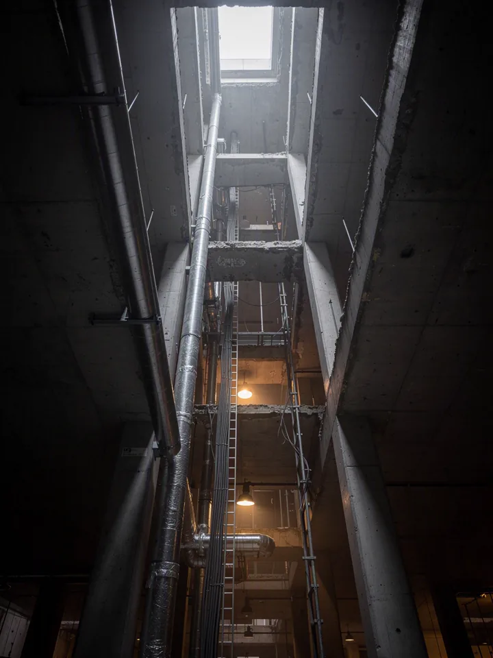
Looking up a vertical service shaft with bundled ducts, pipes and cable ladders
Illustration, AI-generated

Enterprise readiness

  • ISO/IEC 27001
  • GDPR · EU AI Act
  • EU data residency
  • White-label available
Backed by Microsoft for Startups

Run it on one of your own models.

Bring an IFC to the demo and we will run the chain on your building instead of ours - thirty minutes, no sales forms.

Questions

The ones engineers actually ask.

Which standards does the engine actually design to?

Sprinkler to SS-EN 12845, ventilation to BBR 6:25 and SS 25267, plumbing to SS-EN 806 and SS-EN 12056-2, heating to SS-EN 12831, electrical to SS 436 40 00 and SS 437 00 02, fire alarm to SBF 110 and SS-EN 54, fire safety to BBR 5. The clause a figure follows is carried with the figure and printed on the sheet.

What does it need from our model to run?

An IFC with spaces and the building envelope. Room names and areas are read from the model, not guessed - if a space is unnamed, the engine reports it as unnamed rather than inventing a room type for it.

Can we edit the result afterwards?

Yes. The output is an IFC with the MEP model authored into it plus the sheets, so your normal tools open it and your normal review process applies. Nothing is locked to us.

How long does a real project take, not the demo?

The demo model - 7 storeys, 42 apartments - runs the full seven-discipline chain in about 20 seconds. Larger models take longer, roughly with element count. What does not change is that it is one run, not seven handovers.

Who is responsible for the design?

The certified engineer who signs it. QVINTOS produces the engineering basis and shows its work; a person reviews and takes responsibility. Every sheet leaves our engine stamped as a proposal until that happens.

Are the sheets in Swedish?

Yes, always - a Swedish building permit process expects Swedish documents, so the deliverables are produced in Swedish regardless of the interface language. This site is in English; the sheets are not translated.

Early access

Get in the next cohort.

We onboard consultancies and contractors in limited groups so each one gets set up properly, on a real project. The waitlist is how we decide who is next.

By submitting you agree that we may contact you about MEP engineering. No newsletters you did not ask for.